The inside is the limb.
A socket's cavity is the rectified limb, exactly. The studio builds the inside from your scan and your rectification, and shapes only the outside.
Sockets from your scan, built to your recipe and printed in our own carbon-fibre composite.
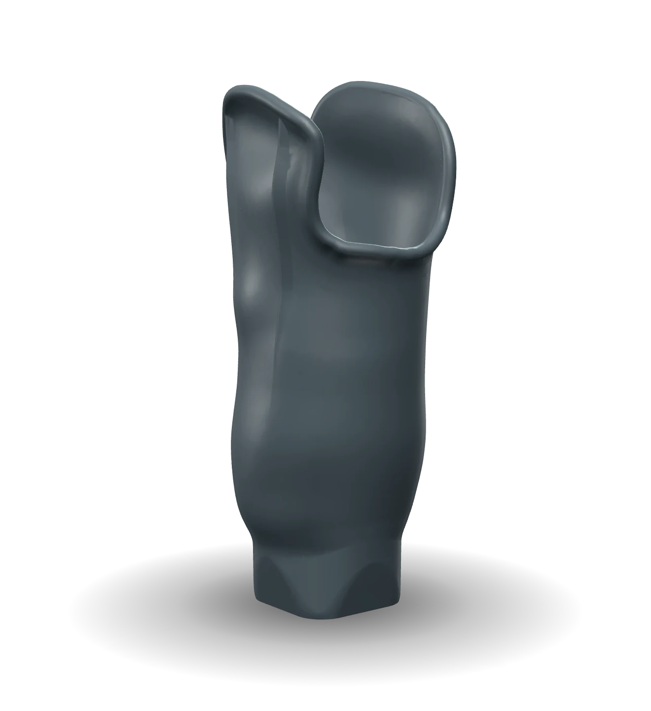 Drag to turn
The socket on this page is a production socket from our farm, printed in carbon-fibre polyamide. Every number here was measured on the file you can turn, by the same code the studio runs on your designs.
A socket's cavity is the rectified limb, exactly. The studio builds the inside from your scan and your rectification, and shapes only the outside.
The line on the socket is its rim, measured. The studio's house trimline is a supracondylar cut like this one, measured off one of our production sockets and stored as 72 numbers, scaled to your patient by a single depth. Lay it on, move its points, draw your own, or cut flat.
This socket was asked for a 4 mm wall, 6 mm at the distal end. The studio casts rays through the shell and reads the wall where it is, not where it was meant to be. The colours are that ray, cast from every point of the surface.
The distal end is solid: a plate with rounded corners that widens as it rises and turns round, a pocket for a steel insert at each corner, and a hole in the centre. Measured on this socket.
A stainless steel insert screws into each pocket: M12 on the outside, where it grips the printed wall, M6 on the inside, where the adapter's screws go. The screws thread into steel, never into the print.
A four-hole adapter sits flat on the plate, its holes over the inserts. Its pyramid is where the rest of the prosthesis joins, the pylon and then the foot, and where the alignment is set.
Each screw goes through the adapter into an insert's M6 thread. Tightened, the socket and the adapter are one part.
Watertight, one body, and exactly five holes through it: four for the bolts and one in the centre. The studio checks every socket it builds the same way, and puts what it found in the report.
Our definitive sockets are printed in a foamed carbon-fibre polyamide that we developed in our own print process, with metal inserts where the bolts go.
A check socket for the fitting, then the definitive socket for daily wear. Same limb, same trimline, your walls.
€120per part
Download only: €19
€390per part
€340 from 5 a month · download only: €49
Prices exclude VAT. Shipping within the Netherlands is included. Designing, approving and every revision are free.
The order is fixed and you move it. Each step has one signature, and going back reopens it.
Drop the scan in. The studio checks the file and tells you what it did to it, and what it would not do.
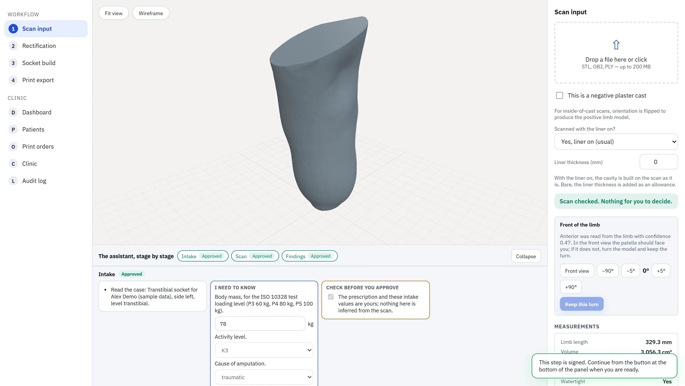
Relief over sensitive structures, build-up over load-tolerant ones, and a map of every change against the scan.
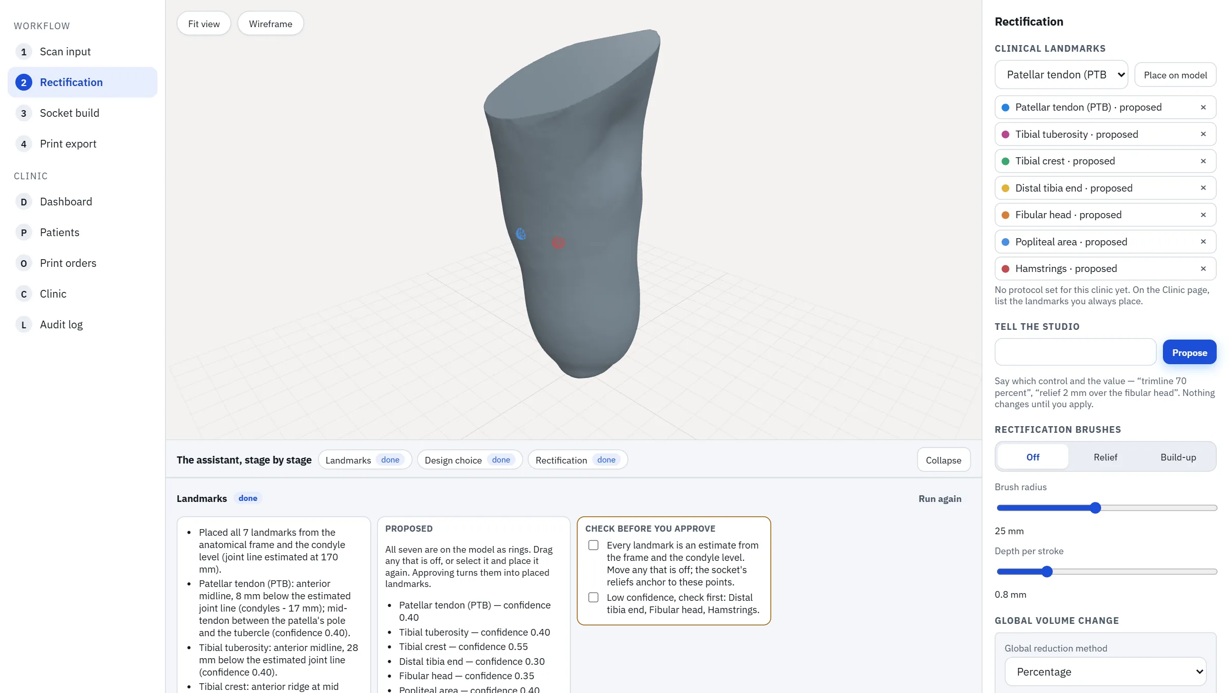
Name a recipe and it fills the step. Nothing is filled in before you choose one, and the wall is always yours.
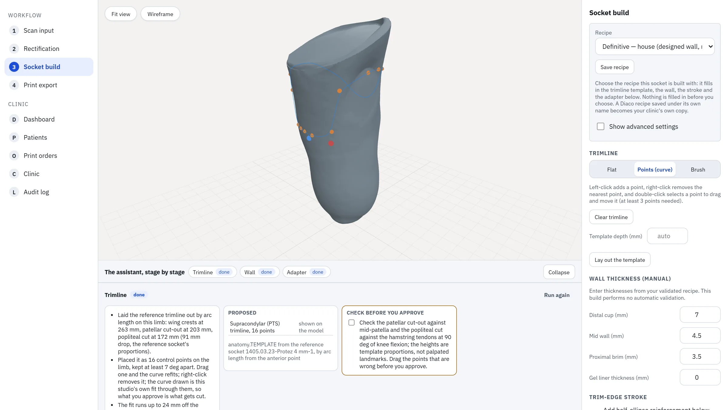
The checks run on every socket built. Then you approve it, and order the part or download it.
Switch it on, and each step runs its stages as it opens. It measures the scan, proposes the landmarks and lays out the trimline template, each proposal with its source.
It asks for the wall and never offers one. A value outside its range is refused with the range, never quietly clamped.
Nothing reaches a control until every review item is ticked and every question is answered. Signing clears the step; moving on is still your click.
Each stage run and each approval is kept with the answers, the edits and who signed, beside the design it belongs to.
A socket's wall thickness is typed by you, or comes from a recipe you name. The studio checks it after the build and never fills it in.
The structural figure is an analytical estimate, not finite element analysis. It is never a substitute for physical testing to ISO 10328.
Classification of Avesta Studio under the EU Medical Device Regulation has not yet been confirmed by a regulatory assessor, and we will not tell you it has.
We set up the software in an afternoon, train your team and make your first parts free. At the end of the month, you decide.